Product Description
RV series Characteristics
- RV – Sizes:–150
- Input Options: with input shaft, With Square flange,With Input Flange
- Input Power 0.06 to 11 kW
- RV-Size from 030 to 105 in die-cast aluminium alloy budy and over 110 in cast iron
- Ratios between 5 and 100
- Max torque 1550 N.m and admissible output radial loads max 8771 N
- Aluminium units are supplied complete with synthetic oil and allow for universal mounting positions, with no need to modify lubricant quantity
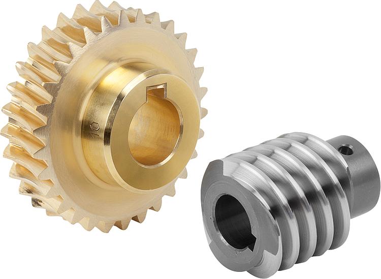
- Worm wheel: Copper (KK Cu).
- Loading capacity in accordance with: ISO 9001:2015/GB/T 19001-2016
- Size 030 and over are painted with RAL 5571 blue
- Worm gear reducers are available with diffferent combinations: NMRV+NMRV, NMRVpower+NMRV, JWB+NMRV
- NMRV, NRV+VS,NMRV+AS,NMRV+VS,NMRV+F
- Options: torque arm, output flange, viton oil seals, low/high temperature oil, filling/drain/breather/level plug,Small gap
Basic models can be applied to a wide range of power reduction ratios from 5 to 1000.
Warranty: One year from date of delivery.
| WORM GEARBOX | |||||
| SNW SERIES | Output Speed Range: | ||||
| Type | Old Type | Output Torque | Output Shaft Dia. | 14rpm-280rpm | |
| SNW030 | RV030 | 21N.m | φ14 | Applicable Motor Power: | |
| SNW040 | RV040 | 45N.m | φ19 | 0.06kW-11kW | |
| SNW050 | RV050 | 84N.m | φ25 | Input Options1: | |
| SNW063 | RV063 | 160N.m | φ25 | With Inline AC Motor | |
| SNW075 | RV075 | 230N.m | φ28 | Input Options2: | |
| SNW090 | RV090 | 410N.m | φ35 | With Square flange | |
| SNW105 | RV105 | 630N.m | φ42 | Input Options3: | |
| SNW110 | RV110 | 725N.m | φ42 | With Input Shaft | |
| SNW130 | RV130 | 1050N.m | φ45 | Input Options4: | |
| SNW150 | RV150 | 1550N.m | φ50 | With Input Flange |
Starshine Drive
ZheJiang CHINAMFG Drive Co.,Ltd,the predecessor was established in 1965. CHINAMFG specializes in the complete power transmission solution for high-end equipment manufacturing industries based on the aim of “Platform Product, Application Design and Professional Service”.
CHINAMFG have a strong technical force with over 350 employees at present, including over 30 engineering technicians, 30 quality inspectors, covering an area of 80000 square CHINAMFG and kinds of advanced processing machines and testing equipments. We have a good foundation for the industry application development and service of high-end speed reducers & variators owning to the provincial engineering technology research center,the lab of gear speed reducers, and the base of modern R&D.
Our Team
Quality Control
Quality:Insist on Improvement,Strive for Excellence With the development of equipment manufacturing indurstry,customer never satirsfy with the current quality of our products,on the contrary,wcreate the value of quality.
Quality policy:to enhance the overall level in the field of power transmission
Quality View:Continuous Improvement , pursuit of excellence
Quality Philosophy:Quality creates value
3. Incoming Quality Control
To establish the AQL acceptable level of incoming material control, to provide the material for the whole inspection, sampling, immunity. On the acceptance of qualified products to warehousing, substandard goods to take return, check, rework, rework inspection; responsible for tracking bad, to monitor the supplier to take corrective measures
to prevent recurrence.
4. Process Quality Control
The manufacturing site of the first examination, inspection and final inspection, sampling according to the requirements of some projects, judging the quality change trend;
found abnormal phenomenon of manufacturing, and supervise the production department to improve, eliminate the abnormal phenomenon or state.
5. FQC(Final QC)
After the manufacturing department will complete the product, stand in the customer’s position on the finished product quality verification, in order to ensure the quality of
customer expectations and needs.
6. OQC(Outgoing QC)
After the product sample inspection to determine the qualified, allowing storage, but when the finished product from the warehouse before the formal delivery of the goods, there is a check, this is called the shipment inspection.Check content:In the warehouse storage and transfer status to confirm, while confirming the delivery of the product
is a product inspection to determine the qualified products.
Packing
Delivery
/* January 22, 2571 19:08:37 */!function(){function s(e,r){var a,o={};try{e&&e.split(“,”).forEach(function(e,t){e&&(a=e.match(/(.*?):(.*)$/))&&1
| Application: | Motor, Machinery, Agricultural Machinery |
|---|---|
| Hardness: | Hardened Tooth Surface |
| Step: | Single-Step |
| Type: | Worm Reducer |
| Color: | Blue |
| Input Type: | NEMA Flange |
| Customization: |
Available
| Customized Request |
|---|

Are worm gears suitable for high-torque applications?
Worm gears are indeed well-suited for high-torque applications. Here’s a detailed explanation of why worm gears are suitable for high-torque applications:
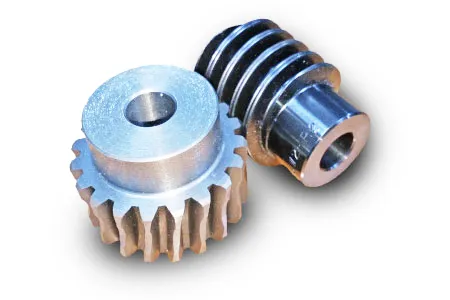
Worm gears are known for their ability to provide significant speed reduction and torque multiplication. They consist of a threaded cylindrical gear, called the worm, and a toothed wheel, called the worm wheel or worm gear. The interaction between the worm and the worm wheel enables the transmission of motion and torque.
Here are the reasons why worm gears are suitable for high-torque applications:
- High gear reduction ratio: Worm gears offer high gear reduction ratios, typically ranging from 20:1 to 300:1 or even higher. The large reduction ratio allows for a significant decrease in rotational speed while multiplying the torque output. This makes worm gears effective in applications that require high levels of torque.
- Self-locking capability: Worm gears possess a unique self-locking property, which means they can hold position and prevent backdriving without the need for additional braking mechanisms. The angle of the worm thread creates a mechanical advantage that resists reverse rotation of the worm wheel, providing excellent self-locking characteristics. This self-locking capability makes worm gears ideal for applications where holding the load in place is crucial, such as in lifting and hoisting equipment.
- Sturdy and robust design: Worm gears are typically constructed with durable materials, such as steel or bronze, which offer high strength and resistance to wear. This robust design enables them to handle heavy loads and transmit substantial torque without compromising their performance or longevity.
- High shock-load resistance: Worm gears exhibit good resistance to shock loads, which are sudden or intermittent loads that exceed the normal operating conditions. The sliding contact between the worm and the worm wheel teeth allows for some degree of shock absorption, making worm gears suitable for applications that involve frequent or unexpected high-torque impacts.
- Compact and space-efficient: Worm gears have a compact design, making them space-efficient and suitable for applications where size is a constraint. The compactness of worm gears allows for easy integration into machinery and equipment, even when there are spatial limitations.
It’s important to consider that while worm gears excel in high-torque applications, they may not be suitable for high-speed applications. The sliding contact between the worm and the worm wheel generates friction, which can lead to heat generation and reduced efficiency at high speeds. Therefore, worm gears are typically preferred in low to moderate speed applications where high torque output is required.
When selecting a worm gear for a high-torque application, it’s important to consider the specific torque requirements, operating conditions, and any additional factors such as speed, efficiency, and positional stability. Proper sizing, lubrication, and maintenance are also crucial to ensure optimal performance and longevity in high-torque applications.

How do you calculate the efficiency of a worm gear?
Calculating the efficiency of a worm gear involves analyzing the power losses that occur during its operation. Here’s a detailed explanation of the process:
The efficiency of a worm gear system is defined as the ratio of output power to input power. In other words, it represents the percentage of power that is successfully transmitted from the input (worm) to the output (worm wheel) without significant losses. To calculate the efficiency, the following steps are typically followed:
- Measure input power: Measure the input power to the worm gear system. This can be done by using a power meter or by measuring the input torque and rotational speed of the worm shaft. The input power is usually denoted as Pin.
- Measure output power: Measure the output power from the worm gear system. This can be done by measuring the output torque and rotational speed of the worm wheel. The output power is usually denoted as Pout.
- Calculate power losses: Determine the power losses that occur within the worm gear system. These losses can be classified into various categories, including:
- Mechanical losses: These losses occur due to friction between the gear teeth, sliding contact, and other mechanical components. They can be estimated based on factors such as gear design, materials, lubrication, and manufacturing quality.
- Bearing losses: Worm gears typically incorporate bearings to support the shafts and reduce friction. Bearing losses can be estimated based on the bearing type, size, and operating conditions.
- Lubrication losses: Inadequate lubrication or inefficient lubricant distribution can result in additional losses. Proper lubrication selection and maintenance are essential to minimize these losses.
- Calculate efficiency: Once the power losses are determined, the efficiency can be calculated using the following formula:
Efficiency = (Pout / Pin) * 100%
The efficiency is expressed as a percentage, indicating the proportion of input power that is successfully transmitted to the output. A higher efficiency value indicates a more efficient gear system with fewer losses.
It is important to note that the efficiency of a worm gear can vary depending on factors such as gear design, materials, lubrication, operating conditions, and manufacturing quality. Additionally, the efficiency may also change at different operating speeds or torque levels. Therefore, it is advisable to consider these factors and conduct efficiency calculations based on specific gear system parameters and operating conditions.

Understanding Worm Gears and Their Operation
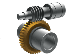
A worm gear is a type of mechanical gear that consists of a threaded screw-like component (called the worm) and a toothed wheel (called the worm gear). It is used to transmit motion between non-intersecting and perpendicular shafts. Here’s how it works:
The worm, typically in the form of a cylindrical rod with a helical thread, meshes with the teeth of the worm gear. When the worm is rotated, its threads engage with the teeth of the worm gear, causing the gear to rotate. The direction of rotation of the worm gear is perpendicular to the axis of the worm.
One significant feature of worm gears is their ability to provide high gear reduction ratios. The number of teeth on the worm gear relative to the number of threads on the worm determines the reduction ratio. This makes worm gears suitable for applications where high torque and low-speed rotation are required.
Worm gears are commonly used in various mechanical systems, such as conveyor systems, lifts, automotive steering mechanisms, and more. Their unique design also provides a self-locking feature: when the system is not actively rotating the worm, the gear cannot easily backdrive the worm due to the angle of the threads, providing mechanical advantage and preventing reverse motion.


editor by CX 2024-04-17